
You are using an out of date browser. It may not display this or other websites correctly.
You should upgrade or use an alternative browser.
You should upgrade or use an alternative browser.
Installing MultiPlusII / How to Disconnect Factory Charger
- Thread starter Focker
- Start date


Jim Beletti
Elite Member
Focker
Well-known member
Yes, I removed the Renogy monitor and put the Touch Screen 50 in its place, it fit perfectly. I will post a photoI like the nice clean install.Did you add a touch screen inside the coach?
")
PrescottNorm
Member
For the 370FB owners that have done or are thinking of this type of installation, I was wondering if you looked into mounting the Victron Hardware in the space between the Basement north wall and the Battery/Generator compartment. Any thoughts on using this area as a location for Victron gear would be appreciated, as it would be close to the existing battery compartment. TIA
Focker
Well-known member
Here is the monitor.I like the nice clean install.Did you add a touch screen inside the coach?
Attachments

Ben and Kathy
Active member
@Jim Beletti I'm doing the same thing, installing a MultiPlus II 2x 120 in our 2021 385FL. It currently has a factory installed 2000W PD Inverter. I will be disconnecting the existing PD Inverter. Am I correct in that in the junction box (from Facebook post in Alliance RV Renovations, Hacks, Mods and Upgrades) should be returned to the state that the picture shows?
We also have a factory installed Onan 5500 generator.
If I understand the wiring path correctly, in the PD Transfer switch, for the upgrade / retrofit I will do three things:
-Ben
We also have a factory installed Onan 5500 generator.
If I understand the wiring path correctly, in the PD Transfer switch, for the upgrade / retrofit I will do three things:
- Take the LOAD line (from the coach) and run it to the primary 120v Output of the MultiPlus II
- Run the LOAD lines from the transfer switch to the Input of the MultiPlus II
- Output from the Generator, Hot 1, Hot 2, combine both and feed both into Hot 1 on the ATS
- This way we can use the full potential of the generator and the MultiPlus II will see 45 Amps of of combined output, Hot 1 and Hot 2, from the generator and can be programmed as such for load sharing
-Ben
Trent Mills
Active member
Could you post the pic you are referencing? For some reason I can't get to it. Thanks!@Jim Beletti I'm doing the same thing, installing a MultiPlus II 2x 120 in our 2021 385FL. It currently has a factory installed 2000W PD Inverter. I will be disconnecting the existing PD Inverter. Am I correct in that in the junction box (from Facebook post in Alliance RV Renovations, Hacks, Mods and Upgrades) should be returned to the state that the picture shows?
We also have a factory installed Onan 5500 generator.
If I understand the wiring path correctly, in the PD Transfer switch, for the upgrade / retrofit I will do three things:
Thanks!
- Take the LOAD line (from the coach) and run it to the primary 120v Output of the MultiPlus II
- Run the LOAD lines from the transfer switch to the Input of the MultiPlus II
- Output from the Generator, Hot 1, Hot 2, combine both and feed both into Hot 1 on the ATS
- This way we can use the full potential of the generator and the MultiPlus II will see 45 Amps of of combined output, Hot 1 and Hot 2, from the generator and can be programmed as such for load sharing
-Ben
Ben and Kathy
Active member
Here it is...Could you post the pic you are referencing? For some reason I can't get to it. Thanks!

Jim Beletti
Elite Member
Ben - I'm not certain what you're referring to. When I removed the factory installed 2000 watt inverter, I removed the 2 Romex lines from the inverter and put them in my own junction box. I spliced it straight-through (black to black, white to white, ground to ground). This binded the branch circuit labled as Inverter, the the string of outlets that were powerable by the inverter. As I am now inverting both AC legs in my coach, all my outlets are inverted now.@Jim Beletti I'm doing the same thing, installing a MultiPlus II 2x 120 in our 2021 385FL. It currently has a factory installed 2000W PD Inverter. I will be disconnecting the existing PD Inverter. Am I correct in that in the junction box (from Facebook post in Alliance RV Renovations, Hacks, Mods and Upgrades) should be returned to the state that the picture shows?
...
-Ben
Ben and Kathy
Active member
Sorry, I wasn't clear, I have two separate questions. You answered the first one, how to undo the old inverter and rewire. I already have a factory installed junction box where the coach wiring runs through it. From there it is wired into the Inverter via two "plugs". See pic below (circled in green)Ben - I'm not certain what you're referring to. When I removed the factory installed 2000 watt inverter, I removed the 2 Romex lines from the inverter and put them in my own junction box. I spliced it straight-through (black to black, white to white, ground to ground). This binded the branch circuit labled as Inverter, the the string of outlets that were powerable by the inverter. As I am now inverting both AC legs in my coach, all my outlets are inverted now.
The second question was about the Onan 5500 generator and the transfer switch. From the a deep dive via Google...
The Onan has two 30 amp circuits for a combined 45amps total output from the generator at any given time. Both of these lines are in phase with each other. Standard 50amp shore power from the pedestal has two 120 volt lines that are out of phase with each other. If the wiring from the generator to the transfer switch is left as is the MultiPlus II will see it as only one 30 amp circuit and ignore the other half believing that it is a 30amp feed off of a 50 amp circuit (like if a 50 to 30amp adapter plug were used for shore power.)
I am wanting to make certain that I am understanding the solution correctly, which is to take L1 and L2 from the generator and combine together into L1 into the transfer switch. Apparently this is a hack/fix recommended by the NRVTA to get the full power use of a generator running through something like a MultiPlus II. I have not been able to verify this anecdotal information however two different popular RV YouTubers have suggested this fix.

Jim Beletti
Elite Member
Hi Ben and Kathy,Sorry, I wasn't clear, I have two separate questions. You answered the first one, how to undo the old inverter and rewire. I already have a factory installed junction box where the coach wiring runs through it. From there it is wired into the Inverter via two "plugs". See pic below (circled in green)
The second question was about the Onan 5500 generator and the transfer switch. From the a deep dive via Google...
The Onan has two 30 amp circuits for a combined 45amps total output from the generator at any given time. Both of these lines are in phase with each other. Standard 50amp shore power from the pedestal has two 120 volt lines that are out of phase with each other. If the wiring from the generator to the transfer switch is left as is the MultiPlus II will see it as only one 30 amp circuit and ignore the other half believing that it is a 30amp feed off of a 50 amp circuit (like if a 50 to 30amp adapter plug were used for shore power.)
I am wanting to make certain that I am understanding the solution correctly, which is to take L1 and L2 from the generator and combine together into L1 into the transfer switch. Apparently this is a hack/fix recommended by the NRVTA to get the full power use of a generator running through something like a MultiPlus II. I have not been able to verify this anecdotal information however two different popular RV YouTubers have suggested this fix.
With regard to 1, the OEM junction box you see there is likely to connect the generator output to the ATS. If there's room in it, you could use that to splice your OEM inverter branch circuit feed and loads wires. Another suggestion is to unplug the white/clear Molex connectors from the coach in/out of the inverter, then swap one end and mate the coach wiring together and do so junction box-less.
With regard to 2, I have no experience in this area but I totally understand what your goal is. To me, it seems viable, but again, caveat: I've got no experience with this and my opinion is my own, not Alliance's.
Focker
Well-known member
I am planning on doing this same "hack" for the generator, I will let you know how it goes. I am doing mine based on the video from Changing Lanes. Do you have the link from the other YouTube person that has done this?Sorry, I wasn't clear, I have two separate questions. You answered the first one, how to undo the old inverter and rewire. I already have a factory installed junction box where the coach wiring runs through it. From there it is wired into the Inverter via two "plugs". See pic below (circled in green)
The second question was about the Onan 5500 generator and the transfer switch. From the a deep dive via Google...
The Onan has two 30 amp circuits for a combined 45amps total output from the generator at any given time. Both of these lines are in phase with each other. Standard 50amp shore power from the pedestal has two 120 volt lines that are out of phase with each other. If the wiring from the generator to the transfer switch is left as is the MultiPlus II will see it as only one 30 amp circuit and ignore the other half believing that it is a 30amp feed off of a 50 amp circuit (like if a 50 to 30amp adapter plug were used for shore power.)
I am wanting to make certain that I am understanding the solution correctly, which is to take L1 and L2 from the generator and combine together into L1 into the transfer switch. Apparently this is a hack/fix recommended by the NRVTA to get the full power use of a generator running through something like a MultiPlus II. I have not been able to verify this anecdotal information however two different popular RV YouTubers have suggested this fix.
View attachment 908
Ben and Kathy
Active member
I've done the hack as shown on Changing Lanes using the newer insulated wiring bus; now to test. Didn't have time to test before assembling everything back together. Quintuple checked and rechecked the wiring paths before buttoning it up. Wasn't happy that I had to use a screw on wire tap and 12 gauge wire extension hack for the new 6/4 I ran in order to be able to connect the Ground wire because the ground bus is only designed for wire smaller than 6 gauge.I am planning on doing this same "hack" for the generator, I will let you know how it goes. I am doing mine based on the video from Changing Lanes. Do you have the link from the other YouTube person that has done this?
Other link: (UPDATE!) Do We Have TOO MUCH POWER? RV Solar, Victron, Lithium Battery Upgrades | RV With Tito DIY (LOL, I hope the time index I captured is not a bad sign...)
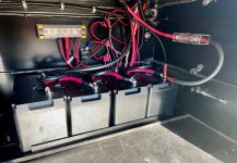
Pic of my transfer switch guts...

Jim Beletti
Elite Member
@Ben and Kathy - What is the wiring hack for the gen? I see the red hot leg going into a splice with a black hot leg coming out of the spice into the gen contactor. Is this more of a wire management hack?
Here's what my ATS looks like. I also have a single-phase gen but I used an autotransformer to create split-phase from it and in that manner, I don't need to reprogram my inverters when I only have single-phase gen or shore input.

Here's what my ATS looks like. I also have a single-phase gen but I used an autotransformer to create split-phase from it and in that manner, I don't need to reprogram my inverters when I only have single-phase gen or shore input.
Last edited:
Ben and Kathy
Active member
The "hack" is to take both hot feeds off the generator and run them in parallel. So in the pick, Red and Black from the Generator line go to the splice bus and a separate short piece of wire runs from the splice bus to L1 of the transfer switch. In the case of my RV's generator wiring, there is one White common for both legs. If that is not clear enough I can mark up a separate picture and post.@Ben and Kathy - What is the wiring hack for the gen? I see the red hot leg going into a splice with a black hot leg coming out of the spice into the gen contactor. Is this more of a wire management hack?
Focker
Well-known member
I've done the hack as shown on Changing Lanes using the newer insulated wiring bus; now to test. Didn't have time to test before assembling everything back together. Quintuple checked and rechecked the wiring paths before buttoning it up. Wasn't happy that I had to use a screw on wire tap and 12 gauge wire extension hack for the new 6/4 I ran in order to be able to connect the Ground wire because the ground bus is only designed for wire smaller than 6 gauge.
Other link: (UPDATE!) Do We Have TOO MUCH POWER? RV Solar, Victron, Lithium Battery Upgrades | RV With Tito DIY (LOL, I hope the time index I captured is not a bad sign...)
Pic of my transfer switch guts...View attachment 987
Ben this is awesome for me to see. I have the same insulated multi-tap connector in my hot little hands ready to install.
Regarding the fat ground wire, I originally planned on using 6/4 but I had a bunch of 6/3 laying around so I used that (a PIA to work with as you know) from the Multiplus II to the transfer switch and I guess in the case of the ground wire it worked out.
I can't wait to hear your feedback on how it works out, I am on pins and needles over here
Focker
Well-known member
Jim this is a good explanation:@Ben and Kathy - What is the wiring hack for the gen? I see the red hot leg going into a splice with a black hot leg coming out of the spice into the gen contactor. Is this more of a wire management hack?
(starts at the 11:02 mark)
Jim Beletti
Elite Member
I get it now. Your gen is a single phase unit with 2 outputs that you are paralleling into the ATS. Makes sense.The "hack" is to take both hot feeds off the generator and run them in parallel. So in the pick, Red and Black from the Generator line go to the splice bus and a separate short piece of wire runs from the splice bus to L1 of the transfer switch. In the case of my RV's generator wiring, there is one White common for both legs. If that is not clear enough I can mark up a separate picture and post.
Ben and Kathy
Active member
Yes very much a PITA. For my short run between the transfer switch and the Multiplus II I bought a better quality 6/4 that was flexible. Regardless, I learned this excellent stiff wire installation hack on YouTube. Posting for all: Victron Multiplus-II: Step-by-Step AC Output/Input Connection Wiring with a Spring Terminal. This was a life saver. Would never have thought of doing this..!Ben this is awesome for me to see. I have the same insulated multi-tap connector in my hot little hands ready to install.
Regarding the fat ground wire, I originally planned on using 6/4 but I had a bunch of 6/3 laying around so I used that (a PIA to work with as you know) from the Multiplus II to the transfer switch and I guess in the case of the ground wire it worked out.
I can't wait to hear your feedback on how it works out, I am on pins and needles over here