• Click here to access some of the presentations made during the 2022 National Rally

Is there a safe way to connect a portable power station to the inverter prep on Alliance Delta

KevinrW26

Member
Hello All,
Sorry if this subject has already been tackled but I would like to know if I can safely hook up the AC output from a portable power station (like the Ecoflow Delta 3 or equivalent) to the Alliance trailer inverter prep jb in the front storage area to power the AC distribution panel when not connected to shore power. Thanks for any feedback or suggestions.
 

KevinrW26

Member
Thanks again Jim but to better understand, what exactly is coming into and going out of the Inverter prep. junction box in the front compartment?
 
I chose to splice male and female plugs into the cord between the shore power inlet and the transfer switch. My power station is an Apex 300 that I leave inline for the camping season and taken indoors during winter hibernation. I have power to my entire panel at all times, just manage high draw devices when boondocking
 

BryanValRox

Elite Member
I chose to splice male and female plugs into the cord between the shore power inlet and the transfer switch. My power station is an Apex 300 that I leave inline for the camping season and taken indoors during winter hibernation. I have power to my entire panel at all times, just manage high draw devices when boondocking
Would you be able to share photos, or provide some additional technicolor on the integration ?
I guess I am really wondering, given the system has individual regular 120 vac outlets, how are you addressing that?
Are you limited to the rating of each outlet(say15-20 amps for example) or are they able to be parallel together externally And tied into the 50 amp service.
Would you be able to use a 15 amp to 50amp pigtail and be limited to 15 amp for example. I understand your managing high load devices via the breaker panel I assume.
 
Would you be able to share photos, or provide some additional technicolor on the integration ?
I guess I am really wondering, given the system has individual regular 120 vac outlets, how are you addressing that?
Are you limited to the rating of each outlet(say15-20 amps for example) or are they able to be parallel together externally And tied into the 50 amp service.
Would you be able to use a 15 amp to 50amp pigtail and be limited to 15 amp for example. I understand your managing high load devices via the breaker panel I assume.
Unfortunately I don’t have pictures right now as it’s tucked away for the winter. Below is a copy/paste from another thread, please let me know if you have further questions

I have the Apex 300 with a B300 on my Paradigm 340. I spliced in male and female plugs into the 8/3 wire that runs between the shore power inlet and the transfer switch. The output of the Apex feeds the entire AC panel which allows a full 12kW pass through when you’re connected to shore power and you can set the input amp limit anytime you’re connected to less than 50amps. I left the original battery where it was so that the converter charges the battery as per normal for all of your DC loads. I also took the factory solar panel wire out of the Victron solar charge controller, attached a XT60 and ran that to the Apex 300 solar input.

As mentioned above, this system allows me to take it in the house during winter storage which is can connect to my Generlink during power outages.

I’ve installed Victron inverter and battery systems on my last two rigs but ending up selling with the rig, now I can take the Bluettie with me if I do sell but not planning to sell my Paradigm!
 

KevinrW26

Member
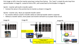
A picture is worth a thousand words.... :geek:

View attachment 5964
Hello Jim,
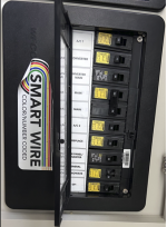
Thank so much, a little clearer now! From your picture, it looks like one of the breakers in the 120 V panel is a signal for the switch and the other is closing a back feed path from inverter to the AC bus. If that is so, why does the feedback not open the switch again like a loop? Also, I attached a pic of the inside of my panel where I think the two breakers you illustrate are numbers 3 and 8 from the top. Which is which versus your pic? How does the switch in your picture prevent both AC from shore power and inverter power from mixing if you plug in shore power and turn on main breaker and inverter breakers? Sorry for all of the questions but thanks again for your help!
 

Attachments

  • Screenshot 2026-11-14 121031.png
    Screenshot 2026-11-14 121031.png
    386.9 KB · Views: 0
Top